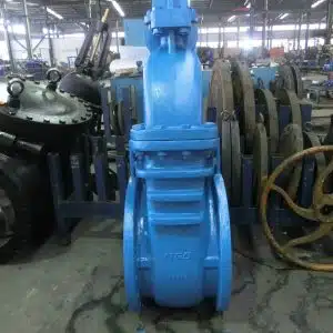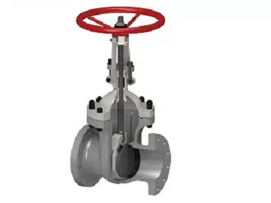
Slide Gate valves are linear motion valves used for full bore fluid flow without any change in direction. They are designed to provide an efficient method for controlling the flow of free-flowing dry bulk materials. It is an ideal valve for transmission and interruption of fluid movement which is mainly suitable for crude, gas pipes, petrochemical oil depots, and other pipelines in the industrial process. The face of this type of valve is mostly parallel and hence they are often referred to as Parallel Slide Gate valves. They are generally either fully open or fully closed and are not normally used to regulate flow. However, slide gate valves can also be installed at the outlet of an oil pump to regulate and control the flow of liquid. A typical slide gate valve is shown in the figure below:

A typical slide gate valve consists of a valve body, valve seat, valve disc, a spindle, gland, and an operating mechanism. The seat and the gate together carry out the function of shutting off the flow of fluid. A 360° surface contact between disk and seat gives proper sealing when the valve is fully closed. This proper mating of a disk to the seal ring ensures that very little or no leakage occurs across the disk when the gate valve is closed. The operation of the valve is mostly by a handwheel, but gear or electric actuators are also very common. The compact structure and smaller operating torque of Slide Gate valves provide good sealing, smaller flow resistant coefficient, and longer service life. Slide Gate valves are most commonly used in pipelines that are designed for the flow of oil or gases like in refineries and petrochemical plants. They are also suitable for use under for wide range of pressure and temperature.
Slide Gate Valve: Structural Classification
- As per the structural characteristics, it can be divided into Standard Slide Gate Valve and Light Slide Gate Valve. Further, Standard Slide Gate Valve can be divided into Slide Gate Valve without diversion hole and Slide Gate Valve with diversion hole.

- It can also be classified according to the seal structure Soft & Hard Dual Sealing Slide Gate Valve and Metal Hard Seal Slide Gate Valve.


- Depending upon the flowing media it can be classified as Parallel Slide Gate Valve for thin fluid and Knife Gate Valve for thick fluid.
Slide Gate Valve: Structural Characteristics
- Embedment of RPTFE and special process treatment of the valve seat provides a soft and hard double sealing.
- The seat and seal of the valve are equipped with a grease injection valve. An on-line emergency auxiliary sealing can be achieved in case of sealing failure.


- The triple seal protection (soft, hard, grease injection), gives the seal more reliability, reduces leakage to absolute zero, and provides longer service life.


- Easy removal of dirt from the sealing surface during the operation of the gate.
- The sealing in the bonnet gland box is either done by a sleeve O-Ring Seal or V-Shaped RPTFE gland seal or flexible graphite.
- The opening & closing torque is 1/3 or ½ times of other industrial valves which are considered very small.
- A soft and hard double sealing surface of the valve seat, flexible graphite gasket between the valve body & the bonnet, and the O-Ring or graphite seal package for the steam seal gives a reliable Fire Safe Design to the valve. This design permits the valve to sustain extremely high temperatures and meet all the requirements for being Fire Resistant as per API 6FA Standards.
- The static electricity generated during operation of the slide valve seat is transmitted to the ground, through the stem nut, bearing, bracket, bonnet, bolt, valve body, and other metal parts connected to the stem. This gives an Anti-Static characteristic to the valve to meet the Ground Static requirements.
- A T-Shaped connection between the valve stem and bonnet is a part of Anti-Blow Stem Design. A 90° chamfered upper seal structure design for the contact part of bonnet, effectively prevent blow out of stem from the bonnet. This provides additional safety while using.

- The edge of the gate has chamfers to prevent the seal from getting damaged during the process of opening & closing.
- The draining & venting arrangement in a slide gate valve is achieved by the drain & vent plug which is located at the bottom of the valve body and the upper part of the bonnet, respectively.
- The protection of stem in a slide gate valve is done by a protection cover that encloses & effectively protects the stem thread and surface from corrosion due to the external environment.
Slide Gate Valve: Working & Performance Characteristics
The performance of a Slide Gate Valve can be widely characterized by various factors ranging from the design to the working environment.
- The parallel faces of the valve enable it to withstand a full pressure difference at both sides of the valve due to which they are often referred to as Parallel Slide Gate Valve.
- Parallel Gate Slide valves utilize a parallel-faced, gate like seating element. It has two parallel disks that are forced on the closure against parallel seats by a spreader.
- The replaceable structure of the dual valve seat provides a function of DBB which also called double block and bleed gate valve.
- A floating valve seat in the design can automatically release the pressure when the middle cavity is over pressured.
- When the middle cavity pressure is greater than the channel pressure, it will get drained to the channel.
- When the upstream pressure of the channel is higher than the downstream pressure (i.e., the valve is closed), the middle cavity pressure will get released to the upstream channel.
- When the upstream pressure of the channel is equal to the downstream pressure (i.e., the valve is fully open), the middle cavity pressure can be discharged by the two-sided channel and the valve seat will automatically reset after the release of pressure.
Sealing Stages in Slide Gate Valve
- When there is no pressure or the pressure inside the valve (middle cavity, inlet, and outlet) is equivalent, the gate is closed, and the RPTFE sealing ring on the surface of the seat provides the initial sealing. The valve seat ring can automatically clean the sealing surface on both sides of the gate, each time it opens or closes.

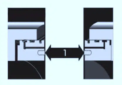
- The pressure of the working media fluid acts on the entrance of the gate, forcing it to move to the PTFE ring on the outlet seat. The gate is pressed against the sealing surface of the metal seat, thus forming a soft and hard double seal. The sealing is achieved in two stages: First sealing is provided by the PTFE and the second sealing is done by the metal itself. The outlet valve seat is also pushed to the end face of the valve body seat hole, where the O-ring ensures sealing between the outer circle of the valve seat and the valve body.

- The release of pressure from the cavity of the valve body forms an inlet seal and the medium pressure acting on the inlet valve seat moves it to the gate. This RPTFE seal & metal to metal sealing facilitates a soft and hard double sealing. Simultaneously, the O-ring ensures sealing between the outer circle of the valve seat and the valve body.

- When the pressure in the cavity of the valve body is greater than the pressure of the pipeline, a pressure difference is created in the cavity. This pushes the inlet valve seat to the end surface of the upstream valve seat hole. The excess pressure inside the valve body in between the upstream seat and the sealing surface of the gate is released into the upstream pipeline which determines the automatic pressure relief function of the valve.

Slide Gate Valve: Advantages & Limitations
Advantages
- Parallel Slide Gate valves require very little space along the pipe axis and the installation procedure is simple & user friendly.
- The minimum flow restriction by the valve makes it ideal for the straight-line flow of fluid.
- The Slide Gate valve provides the ease of cleaning directly by the pipe-clearingmachine due to the diversion hole installed on the pipe.
- The sliding arrangement of the gate on the two seats makes it suitable for use in media with suspended particles.
- The automatic positioning of the sealing surface of the Parallel Slide Gate valve is the most important advantage which makes it suitable for large scale industrial use.
- The valve design permits the valve to sustain extremely high temperatures and prevent the sealing surface of the seat from getting damaged by thermal deformation.
- In cold conditions, the elongation of the stem will not overload the sealing surface even when the valve is closed.
- The Slide Gate valve without a diversion hole does not require high precision for the closing position of the gate due to which an electric Slide valve can use its stroke to control the opening and closing position.
- It can be used to regulate and throttle the flow of fluid if the seat is made into a V-shaped port and is guided closely to the gate.
Limitations
- The major issue with Slide Gate Valve is the slow actuation and its limitation to regulate the media flow effectively.
- It is difficult to achieve a satisfactory sealing when the pressure of the media is low as the sealing force of the metal sealing surface is not sufficient.
- Frequent opening and closing of the slide gate valve may cause the sealing surface of the valve to rapidly wear out when the media pressure is high. The wear down can further aggravate if the sealing surface is not properly lubricated with the system medium or foreign media.
- In the case of a circular gate that moves horizontally on a circular runner, the valve is sensitive to flow control at 50% of the valve closing position.
- The Slide Gate valve is subjected to severe vibrations when the gate interceptshigh-speed and high-density media flow.
- Although these valves have a longer life, carrying out repairs, such as lapping, or grinding is not very easy as compared to other types of valves.
Slide Gate Valve: A Selection Guide
- A single gate or double gate flat valves are most suitable for use in oil and gas pipelines.
- When there is a need to clean the pipeline regularly, a single gate or double gate os & y Slide Gate Valve with diversion hole is preferred.
- Single gate or double gate Slide valves without diversion holes are used in the delivery line and storage equipment of refined oil products.
- In the wellhead devices for oil and natural gas mining, single gate or double gate Slide valves with concealed rod seats and diversion holes are mostly used. They are generally API16A standards with the determined pressure levels of API2000, API3000, API5000, API10000, API15000, and API20000.
- Pipelines with suspended particle media use Knife type Slide Gate valve.
- A single gate or double gate soft seal os & y Slide Gate valve is most suitable for use in the urban gas transmission pipeline.
- Another use of a single gate or double gate open stem Slide Gate Valves without diversion holes is found in urban water supply projects.
Summary
The slide gate valve has a distinct feature of sealing surfaces between the gate and seats which is planar. This makes the valve most suitable for use in a straight-line flow of fluid where minimum restriction is desired. These valves offer a size advantage over other types of valves in terms of space to be allotted between pipe flanges to accommodate the valve. The ease of installation and lesser cost compared to other valve types intended for the same purpose, make this valve most suitable for industrial use such as petrochemical industry, crude, and gas pipes, etc. Ntgd Valve is a professional slide gate valve manufacturer, if you have any question, please feel free to contact us