
Categories
- Blog (116)
- Valve Manufacturers (15)
Valves can be used to control the flow of all kinds of fluids such as air, mud, oil, water, steam, liquid metals, corrosive mediums, and radioactive mediums. Therefore, it is very important to choose the most suitable valves for the piping system. To choose the most suitable valve for the piping system it is important to know the Valve Characteristics and find out steps and criteria for selection.
Industrial valves can be classified depending on various parameters.
a. Automatic Valves: Valves that act on their own depending on the type of the mediums (liquid, gas, etc.).
Examples: Check valves, Safety valves, Regulating valves, Trap valves, Pressure reducing valves, etc.
b. Actuated Valves: Valves that can be operated manually, electrically, hydraulically, or pneumatically.
Examples: Gate valves, Globe valves, Throttle valves, Butterfly valves, Ball valves, Plug valves, etc.
a. Globe Valves: The block part moves along the center of the seat.
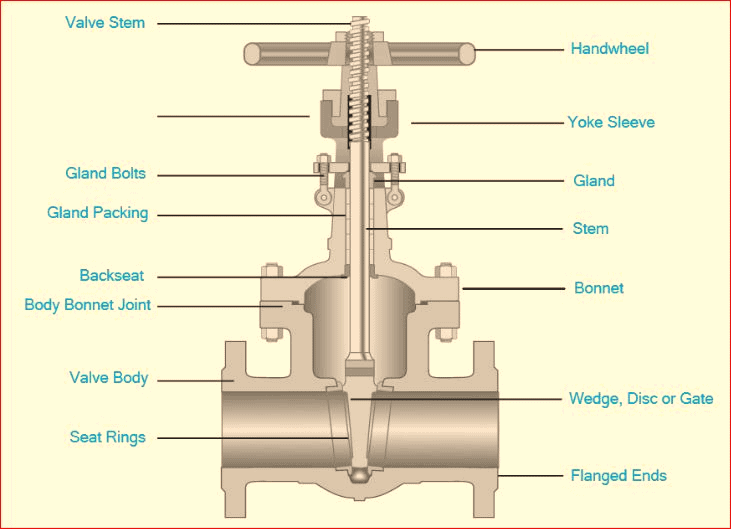
b. Gate Valves: The block part moves along the center of the vertical seat.
c. Plug and Ball Valves: Block part is a plunger or a ball that rotates around its center.
d. Swing Valves: The block part rotates around the axis outside the seat.
e. Butterfly Valves: A disc of the block part rotates around an axis of the seat.
f. Slide Valves: Block part slides in the vertical direction of the channel.
a. Valves to switch on and off: Used to put through or turn off the mediums in the pipelines.
Examples: Globe valves, Gate valves, Ball valves, Butterfly valves, etc.
b. Valves to stop recycling: Used to prevent mediums from backflow
Example: Check valves
c. Valves for Regulating: Used to regulate the pressure and flow rate of the mediums.
Examples: Regulating valves and Pressure reducing valves.
d. Valves for distributing: Used to change the direction of the flowing medium and their distribution.
Examples: Lining T-Cock Valves, Distribution Valves, and Slide valves.
e. Valves for Safety purposes: Used to discharge excessive medium to ensure the safety of the piping system and equipment when medium pressure exceeds specified values.
Examples: Safety valves and Guard valves.
f. Valves for other Special purposes: Trap valves, Vent valves, and Drain valves.
a. Manually driven valves: Driven with the help of handwheel, handle, lever, or chains, etc.
b. Electrically driven valves: Driven with the aid of a motor or other electrical device.
c. Hydraulically driven valves: Driven by water or oil.
d. Pneumatically driven valves: Driven by compressed air.
a. Vacuum valves: Absolute pressure < 0.1Mpa, i.e. valves with 760mm Hg pressure (millimeters of mercury or millimeters of water is used to indicate the pressure).
b. Low-Pressure valves: Valves with normal pressure PN ≤ 1.6 Mpa (steel valves with pressure ≤ 1.6 Mpa are included in the scope.)
c. Medium Pressure valves: Valves with normal pressure between PN 2.5~6.4 Mpa.
d. High Pressured valves: Valves with normal pressure between PN 10.0~80.0 Mpa.
e. Super High-pressure valves: Valves with normal pressure PN ≥ 100.0 Mpa
a. General valves: Valves used where the temperature of the working medium is between 40℃~425℃.
b. High-temperature valves: Valves used where the temperature of the working medium is between 425℃~600℃.
c. Heat resistant valves: Valves used where the temperature of the working medium is over 600℃.
d. Sub-zero valves: Valves used where the temperature of the working medium is between -150℃~-40℃
e. Cryogenic valves: Valves used where the temperature of the working medium is less than -150℃.
a. Small diameter valves: Valves with inside nominal diameter DN<40mm.
b. Medium diameter valves: Valves with inside nominal diameter between DN50~300mm.
c. Large diameter valves: Valves with inside nominal diameter between DN350~1200mm.
d. Oversize valves: Valves with inside nominal diameter between DN350~1200mm.
a. Valves connected with flanges: Valves with connected to the pipes between flanges.
b. Valves connected with screw-threads: Valves with internal or external threads connected to the pipes by threads.
c. Valves welded: Valves with welded junction and welded with pipes.
d. Valves connected with clamps: Valves with clamping port on the valve bodies and connected to the pipes by clamps.
e. Valves with ferrule connection: Valves connected with pipes through ferrule connection.
Valves generally have the following two characteristics:
It determines the main service performance and service range of the valves. The following items belong to this scope:
– Purpose of valves (block valves, regulating valves, safety valves, etc.)
– Types of valves (gate valves, globe valves, butterfly valves, ball valves, etc.)
– The materials of main parts (valve bodies, valve covers, stems, discs, sealing surface).
– Transmission modes of valves.
It determines installation, repair, maintenance, and other methods of valves. The following items belong to the scope:
– The length and overall height of the valve.
– The connection forms with the pipes (flanges, clamps, internal and external threads, and welding, etc.)
– Sealing forms (inserting rings, thread rings, bead welding, spray welding, bodies of valves).
– Valve stem structure (rotating stems, lifting stems, etc.)
1) To confirm both, the applications of the valve in the equipment or devices, and the working conditions of the valve such as applicable mediums, working pressure, and working temperatures, etc.
2) To make sure, both the nominal diameters and connection methods of the pipelines to the valves such as flanges, threads, or welding, etc.
3) To determine the ways to drive the valves i.e., if the valves can be operated manually, electrically, electromagnetically, pneumatically, or hydraulically, electric linkage or electro-hydraulic linkage, etc.
4) To determine, both housings as per medium being transferred by the pipelines, working pressure and working temperature, and the internal parts from gray cast iron, malleable cast iron, nodular cast iron, carbon steel, alloy steel, stainless acid-resistant steel, or copper alloy, etc.
5) To choose the purpose of valves i.e., block valves, regulating valves, safety valves, etc.
6) To ensure the type of valves i.e., gate valves, globe valves, ball valves, butterfly valves, throttle valves, safety valves, pressure reducing valves, steam trap valves, etc.
7) To determine the parameters in case of automatic valves i.e., to determine the allowable flow resistance, discharge capacity, and back pressure, etc., and then to determine the nominal diameters of the pipelines and the diameters of the valve seat holes as per different needs.
8) To determine the geometric parameters of the selected valves i.e., structure length, flange connection form and sizes, the height of the valves after opening and closing, the sizes and numbers of bolt holes connected, and the overall sizes of the valves
9) To take advantage of existing data i.e., valve product catalogs, valve product samples, etc. to select appropriate valve products
After understanding the steps to select a valve, we should further understand the criteria for selecting a valve.
1) To choose as per the purposes, operating conditions, and operation control methods of the selected valves.
2) To choose as per the properties of the working medium i.e., working pressure, working temperature, corrosion performance, the viscosity of the medium, whether it contains solid particles, or whether it is toxic, flammable, explosive, etc.
3) To choose the valve as per requirements of the fluid characteristics i.e., flow resistance, discharge capacity, flow characteristics, and sealing level, etc.
4) To choose as per installation size and external size requirements i.e., nominal diameters, connection methods, connection sizes with pipelines, external sizes, or weight limitation, etc.
5) To choose as per additional requirements for valve product reliability, service life, and explosion-proof performance of their electric devices.
• If the valves are to be used for control purposes, the following additional parameters must be determined:
– methods of operation,
– maximum and minimum flow rate,
– pressure drop for normal flow and at closing,
– maximum and minimum pressure of valve inlets.
• In addition to the above-mentioned basis and steps, understand the internal structures of various types of valves in details for reasonably and correctly selecting the valves, so that the preferred choice of valves can be made.
• Valves are the final control in the pipelines. The opening and closing of the valve control the way of medium flow in the pipelines.
• The shape of the valve flow channels gives the valve certain flow characteristics. This must be taken into account when selecting the most suitable valves for the pipeline system.
– When the valve’s flow channels are straight-through types, their flow resistance is small, they are usually chosen as the valves for stopping and releasing purposes.
– Down-closed valves (stop valves, plunger valves) are less preferred because of their tortuous flow paths and higher flow resistance.
– Valves like block valves can be used where higher flow resistance is allowed.
Valves selected for a certain purpose must be able to easily regulate the flow.
– Downward-closing valves (such as block valves) are suitable for this purpose because their seat sizes are proportional to the stroke of the block parts.
– Rotary valves (plug valves, butterfly valves, ball valves) and flexure body type valves (clamp valves, diaphragm valves) can also be used for throttle control but are only fit for application within a limited range of valve diameters.
– The gate valves are a disk-shaped valve that makes a transverse movement to the circular valve seat. They can only control the flow rate when they are close to the closed position. Hence, they are usually not used for flow control.
As per the requirements of reversing and diverting, valves can have three or more channels. Plug valves and ball valves are more suitable for this purpose. Therefore, most of the valves used for reversing and diverting are selected from one of them. However, in some cases, other types of valves can also be used for reversing and diverting as long as two or more valves are properly connected to each other.
When there are dangling particles in the medium, it is best to use valves with wiping functions while their block parts slide along the sealing surface. If the back-and-forth movement of the block parts is vertical to the valve seat, they can hold particles, therefore these valves are only suitable for non-particle mediums unless the sealing surface materials allow particles to be embedded. Both ball valves and plug valves have a wiping function on the sealing surface during the opening and closing process, hence they are suitable for use in the medium with dangling particles.
Gate valves are the most preferred type of valves. They are not only suitable for mediums such as steam and oil products, but also suitable for mediums containing granular solids and high viscosity. These valves are also suitable for venting and low vacuum systems. For mediums with solid particles, the gate valve bodies should have one or two purge holes. For low-temperature mediums, low-temperature special gate valves should be used.

The globe valve is suitable for pipelines that do not have strict requirements for fluid resistance i.e., the pressure loss. They can be considered for the pipelines or equipment of high-temperature and high-pressure, and pipelines with steam mediums and DN<200mm. For small valves, globe valve can be used, such as pintle valves, valves for instruments, valves for sampling, pressure gauge valves, etc. With flow regulation or pressure regulation, globe valves or throttle valves are preferred for the low accuracy and relatively small diameters. For highly toxic mediums, bellows-sealed globe valves should be used. However, they should not be used for a medium having high viscosity and containing particles that precipitate easily. These valves cannot be used as vent valves and valves for low vacuum systems.
The ball valve is suitable for low temperature, high pressure, and high viscosity media. Most ball valves can be used in media with dangling solid particles and can also be used in powder and granular media as per the requirements of the sealing materials. The full-channel ball valves are not suitable for flow regulation, but they are suitable for occasions requiring quick opening and closing to turn off in emergencies or accidents. Ball valves are recommended in pipelines with strict sealing performance, wear, shrinkage channels, rapid opening and closing actions, high-pressure stop (large differential pressure), low noise, gasification, low operating torque, and low fluid resistance. They are also suitable for light structures, low-pressure stops, and corrosive medium.
While they are the most ideal valves for low temperature, cryogenic medium, low-temperature ball valves with bonnets are used in pipeline systems and devices of the low-temperature medium. When the floating ball valves are selected, the seat materials should bear loads of the ball and the working medium. Large-diameter ball valves require greater torque during operation. The worm gear drive for operation is preferred for ball valves with DN≥200mm. Besides, the ball valves used in the pipeline of highly toxic materials and flammable medium should be fireproof and antistatic.
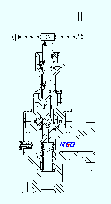
Throttle valves are suitable for places where the temperature of the medium is low, and the pressure is high. They are also suitable for places where the flow rate and pressure need to be regulated. However, they are not suitable for a medium with high viscosity and containing solid particles. Therefore, they cannot be used as isolation valves.

In general, the plug valves are suitable for occasions that require quick opening and closing. They are also suitable for low temperature and high viscosity medium, and for mediums with dangling particles but not suitable for steam and high-temperature mediums.

Butterfly valves are suitable for pipelines with large diameters (such as DN > 600 mm) and short structural length, as well as fast flow regulation and quick opening and closing requirements. They are generally used for water, oil, and compressed air and other mediums with temperature ≤80℃ and pressure ≤1.0MPa. Comparing to the gate valves and ball valves, butterfly valves are suitable for pipeline systems with less strict pressure loss due to their relatively large pressure loss.

Check valves are usually suitable for clean medium, but not suitable for medium containing solid particles and high viscosity.
– For DN≤40mm, lift check valves should be used (only allowed to install in horizontal pipelines).
– For DN=50~400mm, swing lift check valves should be used (installed on both horizontal and vertical pipelines. If installed on vertical pipelines, the direction of medium flow should be from bottom to top)
– For DN≥450mm, buffer type check valves should be used.
– For DN=100~400mm, wafer check valves can also be used.
The swing check valve can be made for a very high working pressure, and the PN can reach up to 42 MPa. As per the materials of housing and the seal, they can be applied to a various working medium such as water, steam, gas, corrosive mediums, oil, etc. and working temperatures in the range between -196 to 800 ℃.
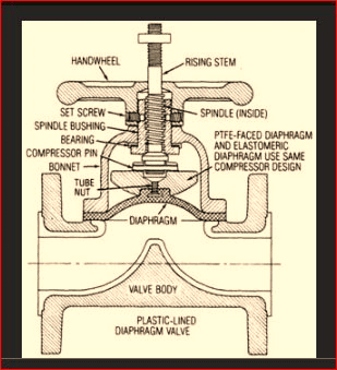
Diaphragm valves are suitable for oil, water, acid medium, and mediums containing dangling particles with working temperatures less than 200℃ and pressure less than 1.0MPa, but they are not suitable for organic solvent mediums and strong oxidant mediums.
– Weir-type diaphragm valves should be selected for abrasive granular medium. Refer to their flow characteristics tables while choosing weir-type diaphragm valves.
– Straight-through diaphragm valves should be used for mediums of viscous fluids, cement slurries, and sediments.
– Diaphragm valves should not be used on vacuum pipelines and vacuum equipment unless they are under specific requirements.
Various types of valves have a wide range of applications and have a high frequency of operation. The applications of valves can be found in various aspects in day to day lives. The role of the valves is very critical to ensure the normal operation of the pipeline system and to prevent the occurrence of the ” dripping and leaking” phenomenon. Therefore, it is very important to understand the structure of the valve, their operation, and their working conditions to select the valve correctly.
 Types of Valves Used In the Chemical Industry